PND-50-14-S
PND-50-14-S Series Parameter Introduction
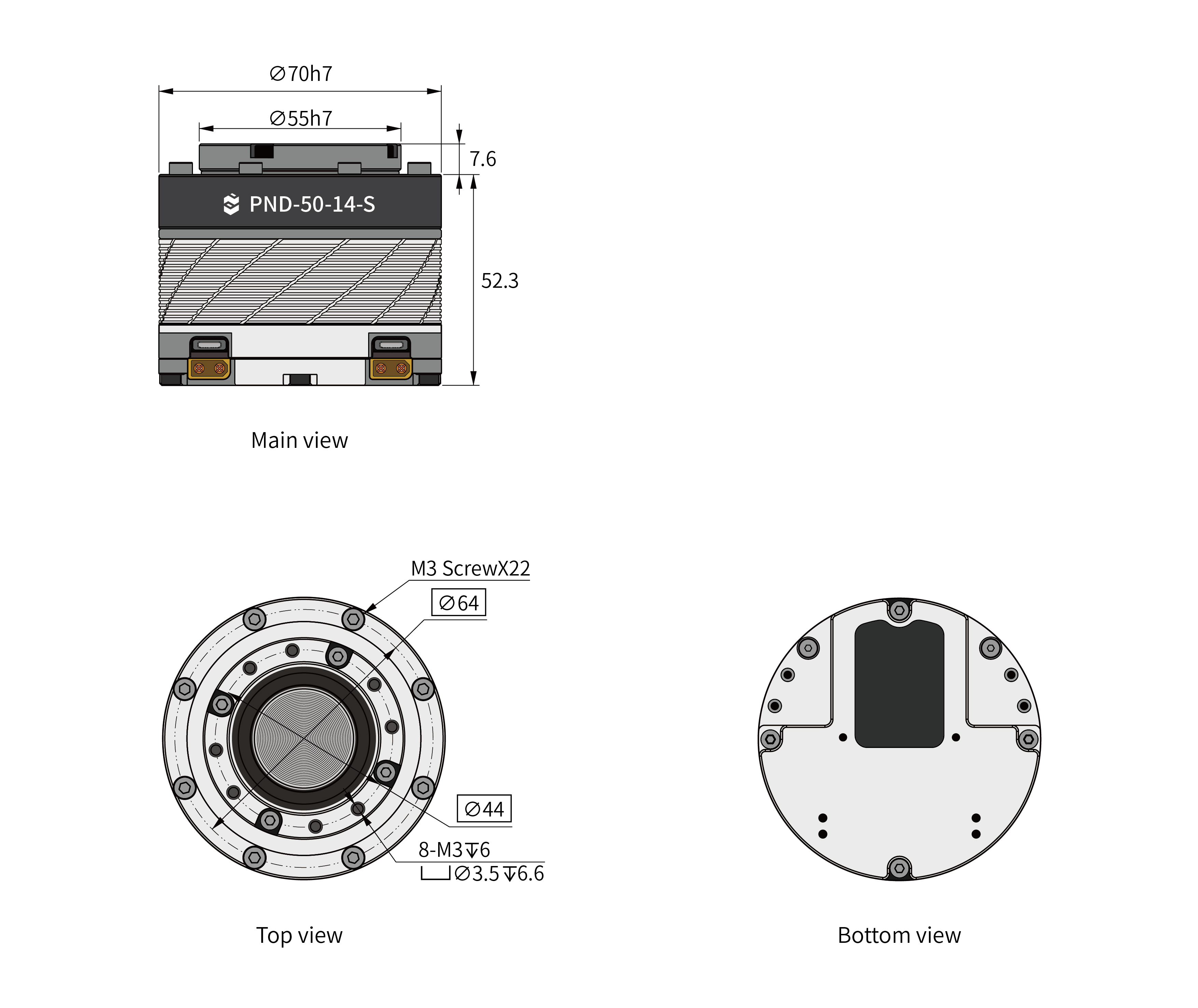
Engineering Drawing
Basic Parameter Table (Motor Output End)
| Motor Parameters | Value | Actuator Parameters | Value |
|---|---|---|---|
| Motor Type | Brushless servo motor | Rated bus voltage | 46.5V DC |
| Rated mechanical output power | 412.1W | Rated phase current | 10A |
| Rated speed | 5500rpm | Peak phase current | 30A |
| No-load speed | 8500rpm | Motor encoder resolution | 4000 Step/turn |
| Rated torque | 0.716N·m | Communication connector | Type-C |
| Peak torque | 2.148N·m | Power connector | XT30 |
| Torque constant | 0.0716N·m/A | Communication protocol | PND-Network |
| Moment of inertia | \(6.03×10^{-5} kg·m^2\) | Operating voltage range | 12~48V DC |
Note
This data is a theoretical value.
Actuator Parameter Table (Actuator Output End)
| Model | Reduction ratio | Rated torque/N·m | Maximum torque/N·m | Rated speed/RPM | Maximum speed/RPM | Torque constant N·m/A | Weight/g | Rated output power/W | Maximum output power/W |
|---|---|---|---|---|---|---|---|---|---|
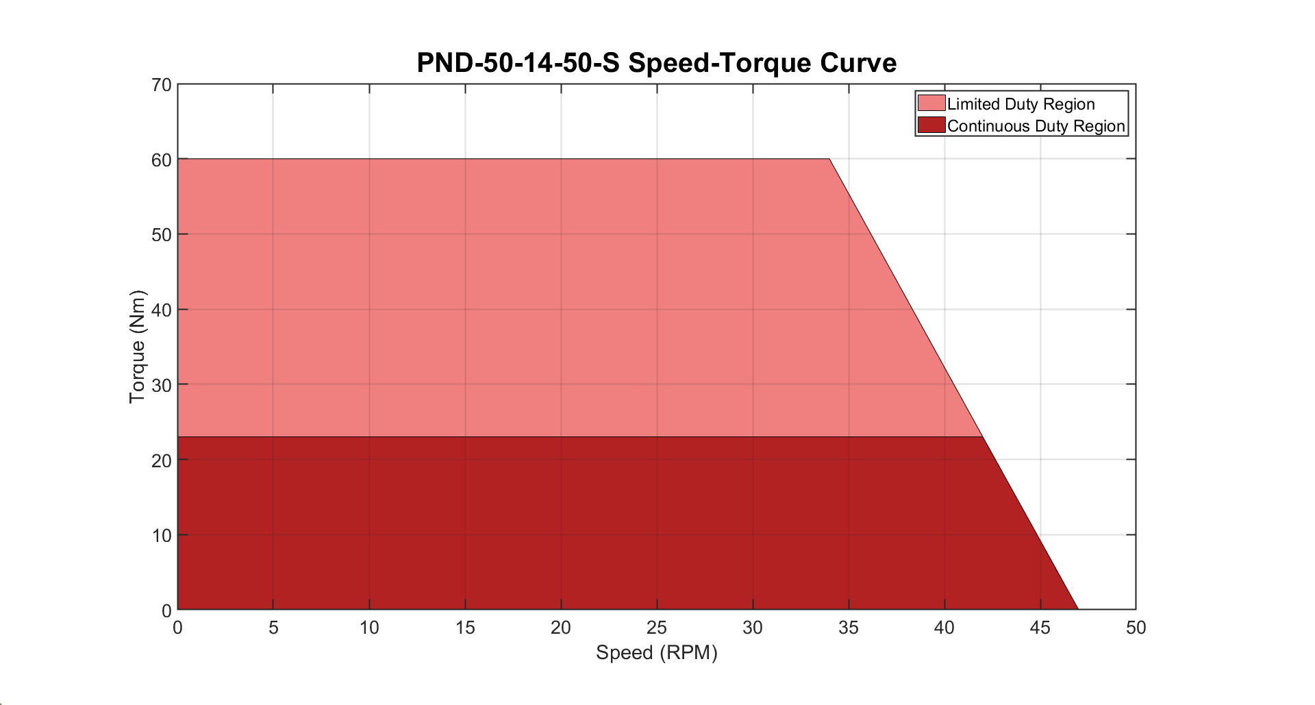
| PND-50-14-50-S | 51 | 23 | 60 | 42 | 47 | 2.3 | / | 103.6 | 213.6 |
Note
The ones marked with * are theoretical values.
Interface Definition
| Name | Specs |
|---|---|
| Physical layer | 10/100Mbps Ethernet or 2.4GHz Wi-Fi |
| Transport layer protocol | UDP |
| Communication port | (realtime) 2333 |
| Communication port | (service) 2334 |
| IP acquisition method | DHCP/Static IP |
| Application layer protocol | Customized JSON |
The power interface is XT30
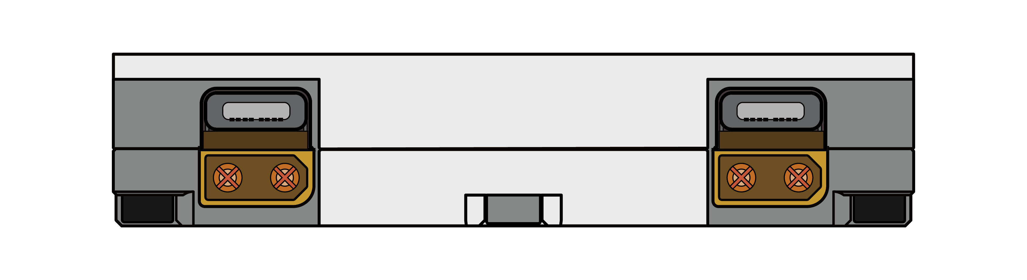
Power/Communication Composite Type - C Pin Definition
Note
The Type-C interface is a special custom interface, not a standard Type-C interface.
| Serial Number | Interface Description | |
|---|---|---|
| Connectors T2 and T3 | B2 | 10/100Mbps Ethernet transmit differential signal TX+ |
| B3 | 10/100Mbps Ethernet transmit differential signal TX- | |
| B10 | 10/100Mbps Ethernet receive differential signal RX- | |
| B11 | 10/100Mbps Ethernet receive differential signal RX+ |
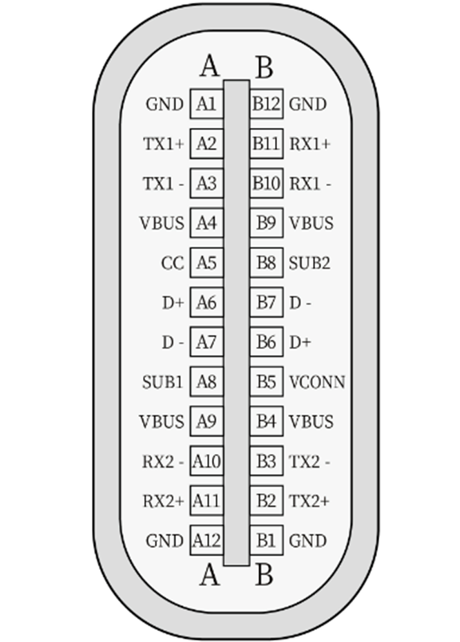
| Serial Number | Interface Description | |
|---|---|---|
| Connector T1 | A1, A12, B1, B12 | GND |
| A4, A9, B4, B9 | 5V | |
| A6, B6 | USB differential signal D+, internally connected to a USB-to-serial chip | |
| A7, B7 | USB differential signal D-, internally connected to a USB-to-serial chip | |
| A2 | 10/100Mbps Ethernet transmit differential signal TX+ | |
| A3 | 10/100Mbps Ethernet transmit differential signal TX- | |
| B10 | 10/100Mbps Ethernet send differential signal RX- | |
| B11 | 10/100Mbps Ethernet send differential signal RX+ |
3D Model
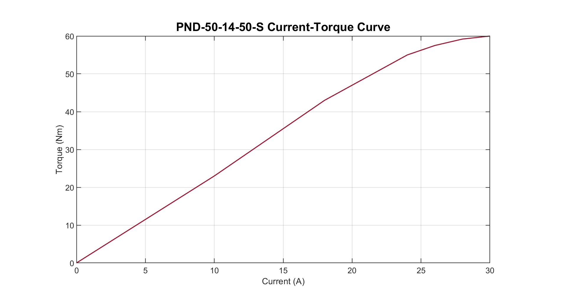
Performance Curve