🛠️ PND Adam U Deploy SDK
PND Upper-Body Robot Development Kit Supports the complete workflow from source code building to simulation & real robot control.
🏗️ Building from Source Code
Environment Requirements
- Operating System: Ubuntu 22.04 (Mac/Windows are not currently supported)
- Network Configuration: For real robot operation, the development machine and the robot's NUC must be on the same local area network.
🐢 Mujoco Deployment Process
1. Environment Preparation
- Mujoco Version:
3.2.0 - Git LFS for large file support:
2. Download and Launch pnd_adam_u_mujoco (Simulation Node)
- Open a terminal
git clone https://github.com/pndbotics/pnd_adam_u_mujoco.git && cd pnd_adam_u_mujoco
sudo ./run_pndrobotros2.sh mujoco
Note: The node is ready when the terminal prints
TRUE
3. Download and Run pnd_adam_u_deploy (Control Node)
- Open a new terminal
git clone https://github.com/pndbotics/pnd_adam_u_deploy && cd pnd_adam_u_deploy
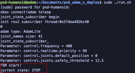
colcon build && sudo ./run.sh
Status Note: The control is ready after
FSM start!is displayed
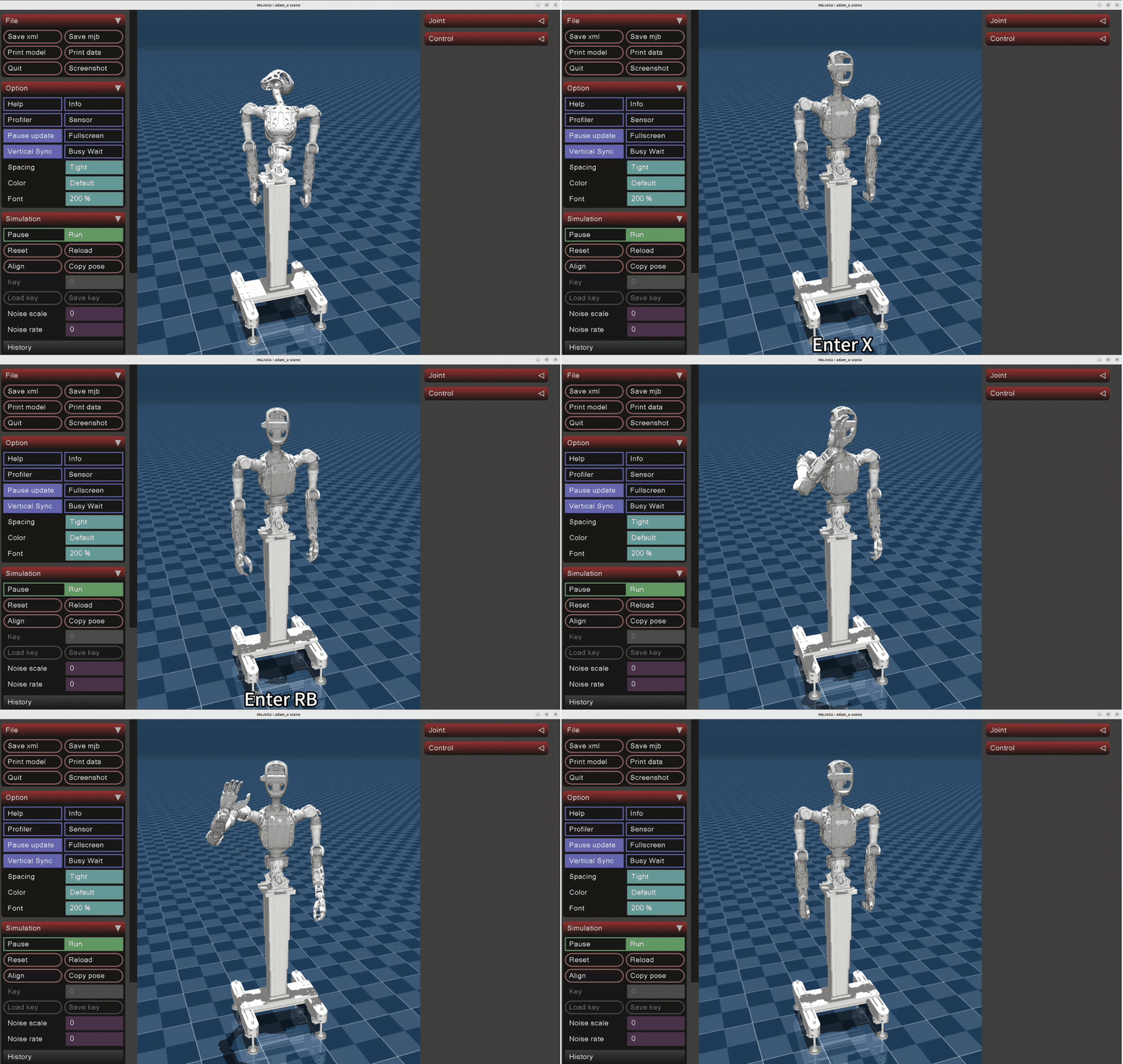
4. Joystick Control
- Ensure both the simulation and control nodes are running
- Ensure the joystick is successfully connected to the computer
- Control sequence: Once in simulation, press A → X → RB
🐢 Real Robot Deployment Process
1. Start the Robot Control Node
Open a terminal

Note: The node is ready when the terminal prints
TRUE
2. Download and Run deploy
Open a new terminal
ssh pnd-humanoid@192.168.41.xx
git clone https://github.com/pndbotics/pnd_adam_u_deploy && cd pnd_adam_u_deploy
colcon build && sudo ./run.sh

Status Note: The control is ready after
FSM start!is displayed
3. Joystick Control
- Ensure the control node is running
- Ensure the joystick is successfully connected to the robot's NUC
- Control sequence: Once control is active, press A → X → RB

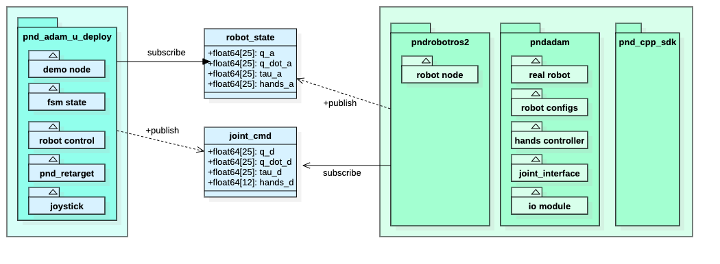
📦 Module Diagram

🔗 Joint Data Interface
1. Subscribe to /joint_cmd (Command Downstream)
| Field | Dimension | Meaning |
|---|---|---|
q_d |
25 | Joint Desired Position |
q_dot_d |
25 | Joint Desired Velocity |
tau_d |
25 | Joint Desired Torque |
hands_d |
12 | Hand Desired Position |
2. Subscribe to /robot_state (Actual State)
| Field | Dimension | Meaning |
|---|---|---|
q_a |
25 | Joint Actual Position |
q_dot_a |
25 | Joint Actual Velocity |
tau_a |
25 | Joint Actual Torque |
hands_a |
12 | Hand Actual Position |
🦾 Dimension Mapping Explanation
Body Joints (25 Dimensions)
| Indexes | Joint Name | Part |
|---|---|---|
| 0–5 | Base Data | Fixed |
| 6 | waistRoll |
Torso |
| 7 | waistPitch |
Torso |
| 8 | waistYaw |
Torso |
| 9 | neckYaw |
Neck |
| 10 | neckPitch |
Neck |
| 11–17 | Left Arm Joints | Left Arm |
| 18–24 | Right Arm Joints | Right Arm |
Hand Data (12 Dimensions)
| Index Range | Corresponding |
|---|---|
| 0–5 | Left Hand |
| 6–11 | Right Hand |
Single Hand Joint Mapping
| Index | Part |
|---|---|
| 1 | Pinky |
| 2 | Ring |
| 3 | Middle |
| 4 | Index |
| 5 | Thumb |
| 6 | Lateral |
🎮 Joystick Control Protocol
Button Function Mapping
| Button Combination | Function Description |
|---|---|
| A | All joints return to zero |
| X | Toggle Ready state |
| B | Damping mode lock |
| LB + RB | Toggle joint power (Disabled) |
Data Structure Definition
#define XBOX_TYPE_BUTTON 0x01
#define XBOX_TYPE_AXIS   0x02

// Button mapping
#define XBOX_BUTTON_A     0x00
#define XBOX_BUTTON_B     0x01
#define XBOX_BUTTON_X     0x03
#define XBOX_BUTTON_Y     0x04
#define XBOX_BUTTON_LB    0x06
#define XBOX_BUTTON_RB    0x07
#define XBOX_BUTTON_START 0x02
#define XBOX_BUTTON_BACK  0x05
#define XBOX_BUTTON_HOME  0x08
#define XBOX_BUTTON_LO    0x09  /* Left stick button */
#define XBOX_BUTTON_RO    0x0a  /* Right stick button */

// Stick and D-pad mapping
#define XBOX_AXIS_LX 0x00
#define XBOX_AXIS_LY 0x01
#define XBOX_AXIS_RX 0x02
#define XBOX_AXIS_RY 0x03
#define XBOX_AXIS_LT 0x05
#define XBOX_AXIS_RT 0x04
#define XBOX_AXIS_XX 0x06
#define XBOX_AXIS_YY 0x07

// Value definitions
#define XBOX_AXIS_VAL_UP    -32767
#define XBOX_AXIS_VAL_DOWN   32767
#define XBOX_AXIS_VAL_LEFT  -32767
#define XBOX_AXIS_VAL_RIGHT  32767
#define XBOX_AXIS_VAL_MIN   -32767
#define XBOX_AXIS_VAL_MAX    32767
#define XBOX_AXIS_VAL_MID    0x00

// Structure
typedef struct xbox_map {
  int time;
  int a, b, x, y;
  int lb, rb, start, back, home;
  int lo, ro;
  int lx, ly, rx, ry;
  int lt, rt, xx, yy;
} xbox_map_t;
🔣 Kp / Kd Parameter Explanation
In Simulation (Isaac Gym)
PD Controller:
\(\tau = K_p e_p + K_d e_v\)
- $K_p$: Stiffness
- $K_d$: Damping
- $e_p$: Position error
- $e_v$: Velocity error
On Real Robot Actuators
PID Controller:
\(I = P_p P_v e_p + P_v e_v\) \(\tau' = g I K_t = g(P_p P_v K_t e_p + P_v K_t e_v)\)
- $P_p$: Position loop proportional parameter
- $P_v$: Velocity loop proportional parameter
- $g$: Gear ratio
- $K_t$: Torque constant
Sim-to-Real Parameter Relationship
When $ \tau = \tau' $ is satisfied:
\(K_p = g P_p P_v K_t\) \(K_d = g P_v K_t\) \(P_v = \frac{K_d}{K_t g}\) \(P_p = \frac{K_p}{K_d}\)