Actuator network connection
Connect actuators to PND-Network
PNDrive actuators can be connected by both wire and wireless. The actuators are set to DHCP mode by default. Therefor, the router should enable its DHCP service (1), or use a computer that has DHCP service installed to allocate IP address for the actuators.
- DHCP (Dynamic Host Configuration Protocol), is a network protocol for local area networks. It works using the UDP protocol. It quickly and automatically assigns IP addresses to the network. DHCP can help allocating IP addresses and related IP information to computers in the network.
Note
For the application that requires high reliability and low latency, we suggest to use wired connection(loopback communication latency less than 4ms). On wireless connection, communication latency would be over 10ms.
Wired Connection
The PNDrive actuator usually has 1-3 Type-C port for communication. For the actuator that has only one Type-C, connect one of the Type-C port to the Type-C plug on the compound cable. Connect the RJ45 plug of the compound cable to RCU-4, and connect the ethernet port on RCU-4 to the external network. If the PNDrive actuator have more than 1 Type-C ports, two of the Type-C ports can be used for cascade connection. After the cables are all connected, power on the RCU-4 and wait util the system is booted, then enable the power supply for actuators. If the actuator blinks purple rapidly, it indicates that it is still connecting through the cable. If connected, it would glow purple slowly. If the IP allocation failed, the actuator will switch to wireless connection, and the light will turn from blinking purple rapidly to blinking blue rapidly.
Note
The PSA actuators's IP allocation method of wired connection could be Dynamic IP or Static IP.
-
Dynamic IP Connection
The PSA actuators are set to Dynamic IP by default. It needs power support and network communication. The customer needs to prepare a computer, router, and power supply. The power cable should have a XT30 connector. The connection diagram is shown below:
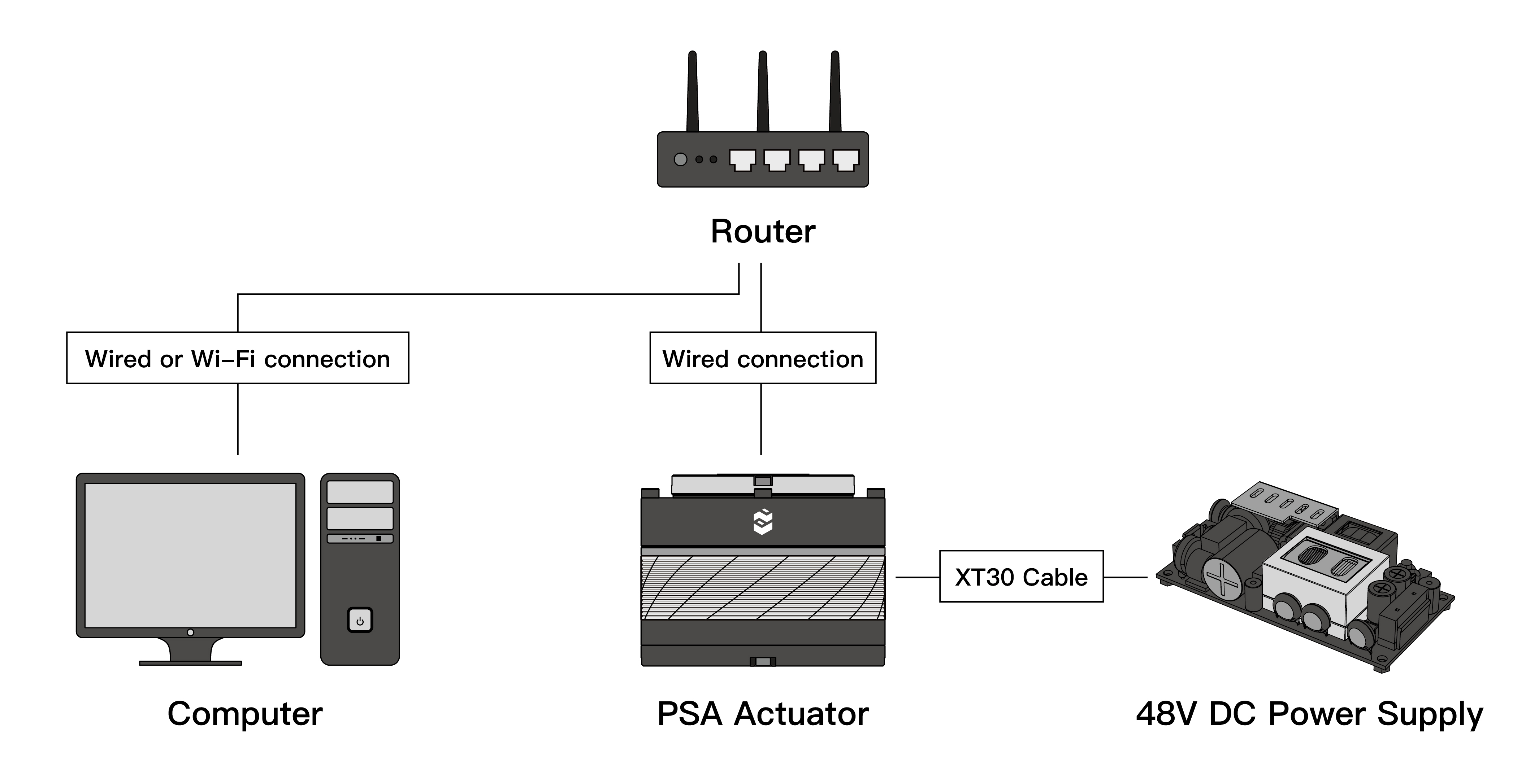
-
Static IP Connection
When in Dynamic IP mode, the instruction to modify Static IP is shown HERE.
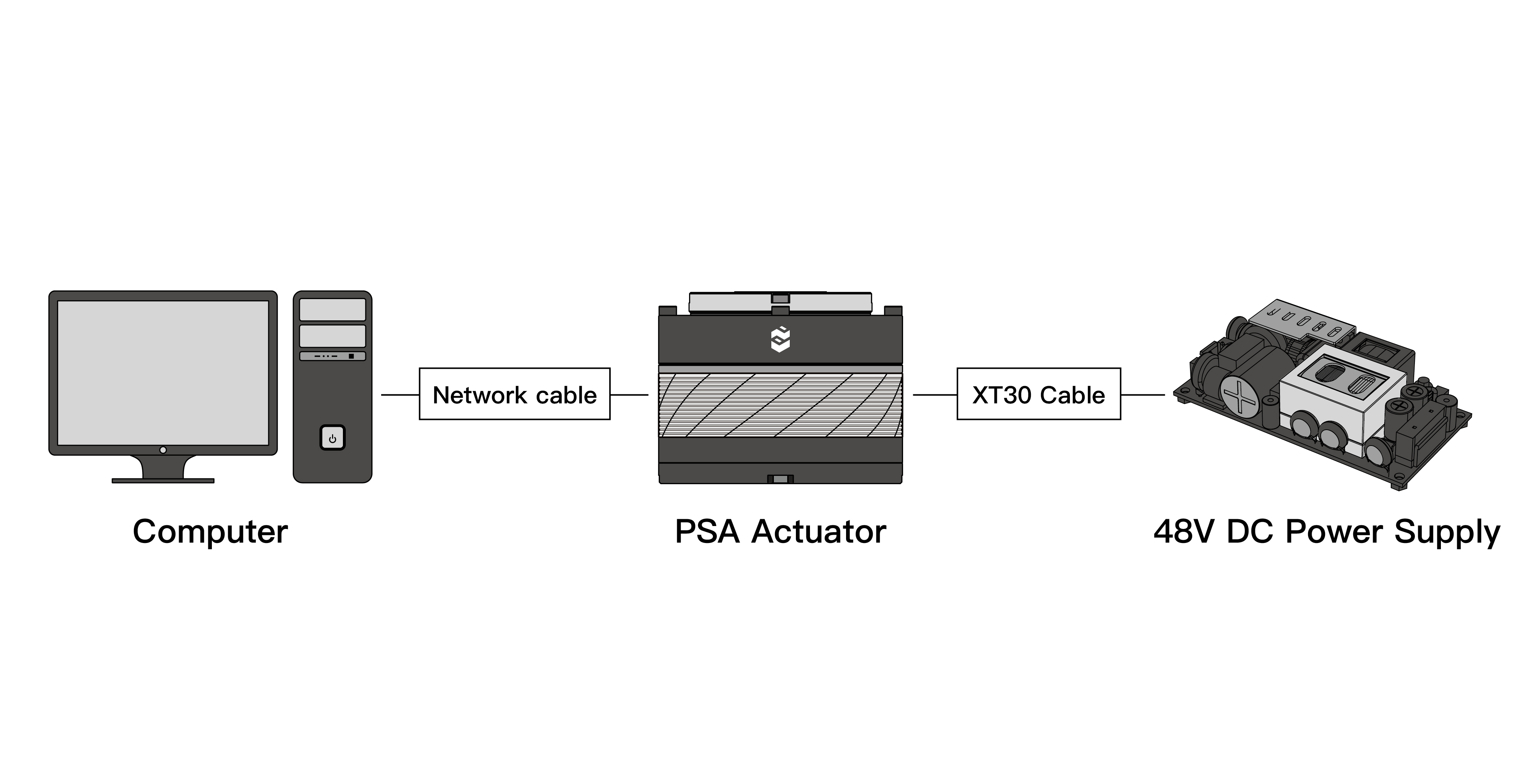
The Static IP mode is point-to-point direct connection. Compared to Dynamic IP mode, a router is not required. The diagram is shown below:
Wireless Connection
In the wired connection mode, use PAS to set the SSID and password for the actuator. Unplug the Ethernet cable after the setup is finished, and then restart the actuator. Wait for 10 seconds until the light turns to blinking blue rapidly, which indicates that the actuator is in the wireless mode. If the light turns to glowing blue, the wireless connection is completed. For the detailed instruction of PAS, please checkHERE.
Note
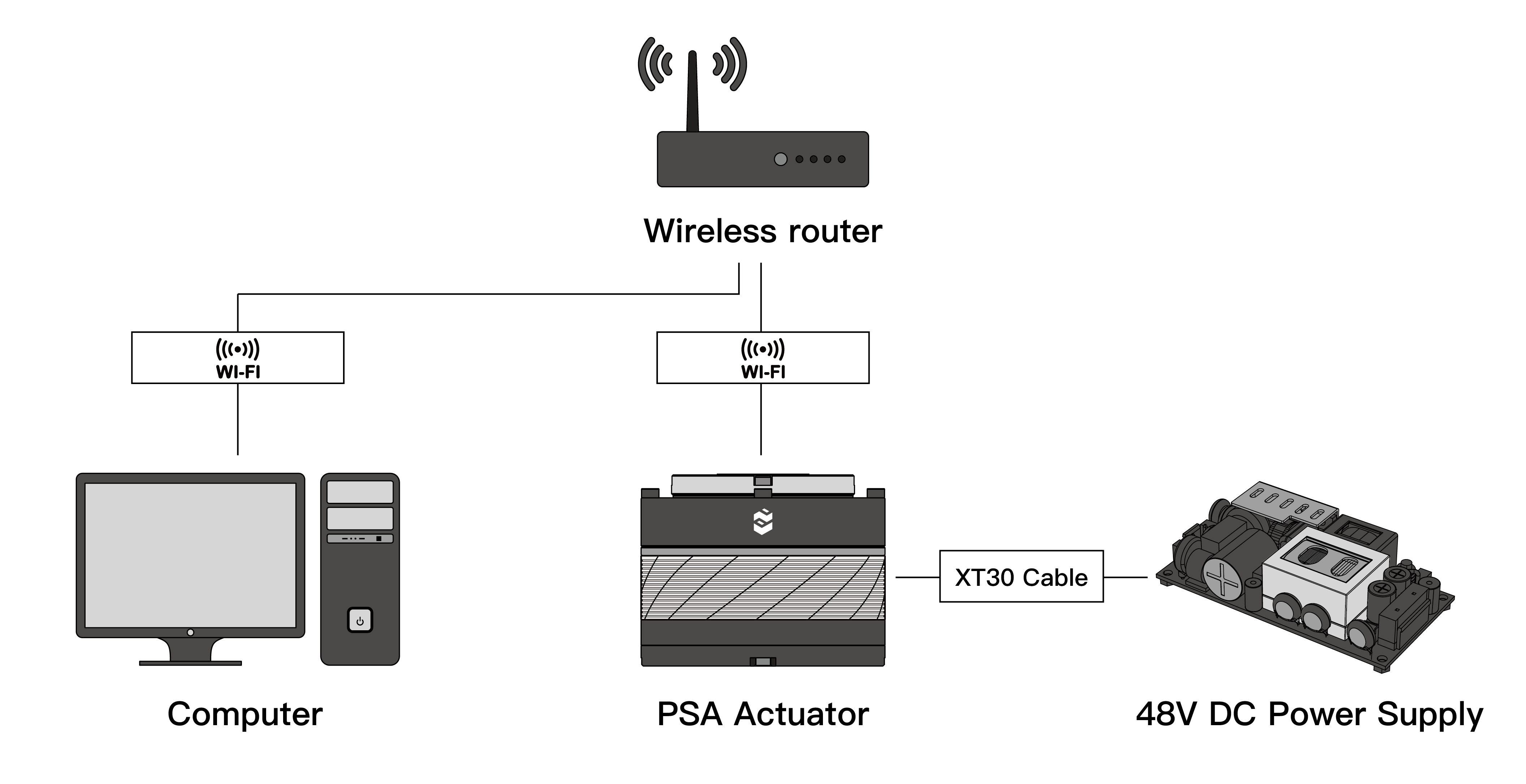
In wireless mode, the actuator must be in Dynamic IP mode and must be in the same network with your computer.
Wireless connection diagram is shown below:
Reset IP Address
When the static IP address of the PSA actuator is forgotten or the IP address is set incorrectly, causing inability to access the PSA actuator, the IP address can be reset to fix the problem. (This method only works on PSA version 2.0 or above)
- Use the USB cable to connect the actuator's Type-C port to your computer, and open the serial port tool to communicate.
- Send IP command through serial port, the actuator will return its current IP address.
- Send reset command through serial port, the actuator's IP will be rested and will be set to Dynamic IP mode.
Mechanical Installation
Secure the actuator
The threaded holes on the outer ring of the actuator are used to install the actuator to other mechanical components or devices.
Use M3 screws to secure the actuator to the working part of the machine. The effective depth of the thread needs to reach 5mm - 6mm (approximately 10 - 12 turns) to ensure the perpendicularity of the actuator to the installation surface of the machine.
Secure the output flange
The threaded holes on the inner ring of the actuator are for outputting power and are used for connecting external moving parts.
Use M3 screws to connect the output flange and the external moving parts. The effective depth of the thread needs to reach 4mm - 5mm (about 8 - 10 turns) to ensure the perpendicularity of the actuator to the installation surface and the coaxiality of the moving parts.
Verify the interference
After the installation, manually rotate the external moving parts to verify whether there is interference or jamming.
Software installation
Software download and installation
Instructions
In Wired connection mode(Dynamic IP)
After the actuator is powered on, the light will glow purple rapidly, which indicates it is connecting to ethernet. The light will glow purple slowly if succeeded. If IP allocation failed, the actuator will attempt to connect through wireless connection after 10 seconds automatically. The light will change from blinking purple rapidly to blinking blue rapidly.
Note
If the connection to the wired mode failed, you can restart the actuator to attempt to connect via wired connection again.
In Wireless connection mode
After starting the PSA actuator, observe the indicator light. If it starts to flash blue rapidly from purple and then flashes slowly in blue, it indicates that the wireless connection is successful.
Note
If the light keeps flashing rapidly in blue, it indicates that the PSA actuator has been searching for WIFI. This might be caused by incorrect SSID and password. Please reconfirm.