RCU-8
Introduction to RCU-8 Parameters
Introduction
The Robot Control Unit-8 (RCU-8) is a power supply module that supports the power supply of the PSA series actuators. It integrates functions such as Ethernet UDP communication configuration and power braking. It supports 8 standard RJ45 communication interfaces, 2 XT60 and 6 XT30 power output interfaces, providing reliable protection for various power consumption needs of multiple actuators.
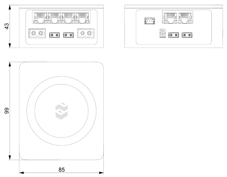
Engineering Drawing
Interface Specifications
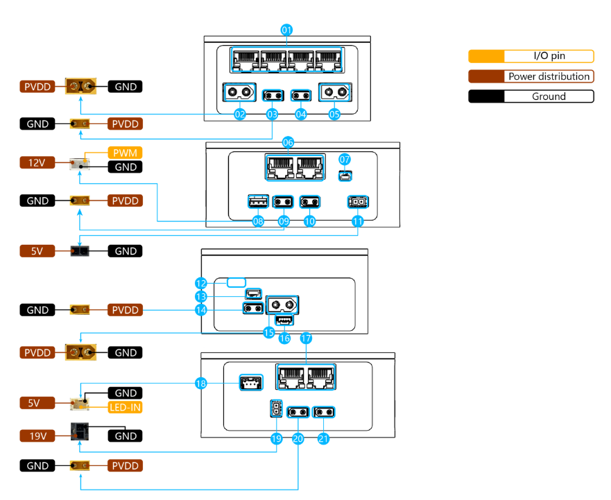
| Serial Number | Type | Interface Description |
|---|---|---|
| ①⑥⑰ | I/O | 8 standard RJ45 connectors, supporting 10/100/1000M Ethernet. |
| ②⑤ | O | 2 XT60 connectors, outputting 12~48V DC. |
| ③④⑨⑩⑳ (21) | O | 6 XT30 connectors, outputting 12~48V DC. |
| ⑦ | I | Start switch, SM02B-GHS-TB(LF)(SN) interface. Short press and release for power on/off function; long press (more than 5s) and release, the RCU enters sleep mode, and all external power supplies are turned off. When entering sleep mode, all external systems need to be turned off to avoid equipment failure caused by forced power off. When short pressing and releasing, it enters the normal working mode from the sleep mode. |
| ⑧ | O | XH2.54 interface, outputting 12V fan power, PWM control. |
| ⑪ | O | 1 436500200 connector, 5V/7A power output. |
| ⑫ | I/O | Type-C USB interface. |
| ⑬ | I | Emergency stop switch, SM03B-GHS-TB(LF)(SN) connector. When the emergency stop switch is pressed, the power on/off function of the start switch is disabled. Only when the emergency stop switch is open, the power on/off function of the start switch can be used normally. |
| ⑭ | I | 1 XT30 connector, battery charging interface. |
| ⑮ | I | 1 XT60 connector, inputting 12~48V DC. |
| ⑯ | I/O | Communication port, SM04B-GHS-TB(LF)(SN) connector. RS485/TTL communication port with the battery. |
| ⑱ | O | 1 5023520300 connector, outputting magic lantern signal. |
| ⑲ | O | 1 430450200 connector, 19V/7A power output. |
Indicator Status Description
| Serial Number | Indicator Status | Meaning |
|---|---|---|
| 1 | Purple, fast blinking | Wired Ethernet connection in progress. |
| 2 | Purple, slow blinking | Wired Ethernet connection successful. |
| 3 | Cyan-blue, fast blinking | Wi-Fi connection in progress. |
| 4 | Cyan-blue, slow blinking | Wi-Fi connection successful. |
| 5 | Red, fast blinking | RCU error. |
| 6 | Emerald green, fast blinking | OTA upgrade in progress. |
| 7 | Dark blue, slow blinking | Login verification successful. |
| 8 | Yellow, fast blinking | Configuration mode. |
The RCU-8 control circuit board needs to pass online verification to be used normally. Therefore, when using the RCU-8 control circuit board, it needs to be connected to the external network. On the RCU-8 control circuit board, it can be judged by the blinking mode of the magic lantern. When the magic lantern blinks slowly in dark blue, it indicates that the verification is successful.
Hint
The networking methods of the RCU-8 control circuit board are as follows. According to the IP address, it is divided into dynamic IP and static IP modes.
- In dynamic IP mode, simply connect to the external network.
- In static IP mode, there are two types: one is that the static IP (such as
192.168.1.200) and the external network IP (such as192.168.1.1) are in the same network segment, that is, the first three numbers of the IP address are the same. In this case, simply connect to the external network. - The other is that the static IP (such as
10.10.10.200) is different from the external network IP (such as192.168.1.1). In this case, routers and other equipment need to be added for conversion. - The way to add a router is that the router connects to the external network through wired or wireless means, and the router IP address (such as
10.10.10.1) is set to be the same as the first three digits of the static IP address of the RCU-8 control circuit board. - The way to use a computer is that the computer connects to the external network through wireless and connects to the RCU-8 control circuit board through wired. The IP address of the computer's wired connection (such as
10.10.10.199) is in the same network segment as the static IP address of the RCU-8 control circuit board (such as10.10.10.200). And install the function of converting wireless traffic to wired on the computer.
Web Service Description
Use a browser to open the current IP address of the RCU (e.g., 10.10.10.200) to access the built-in web service of the RCU, view the current running status of the RCU, operate the RCU or modify the RCU configuration.
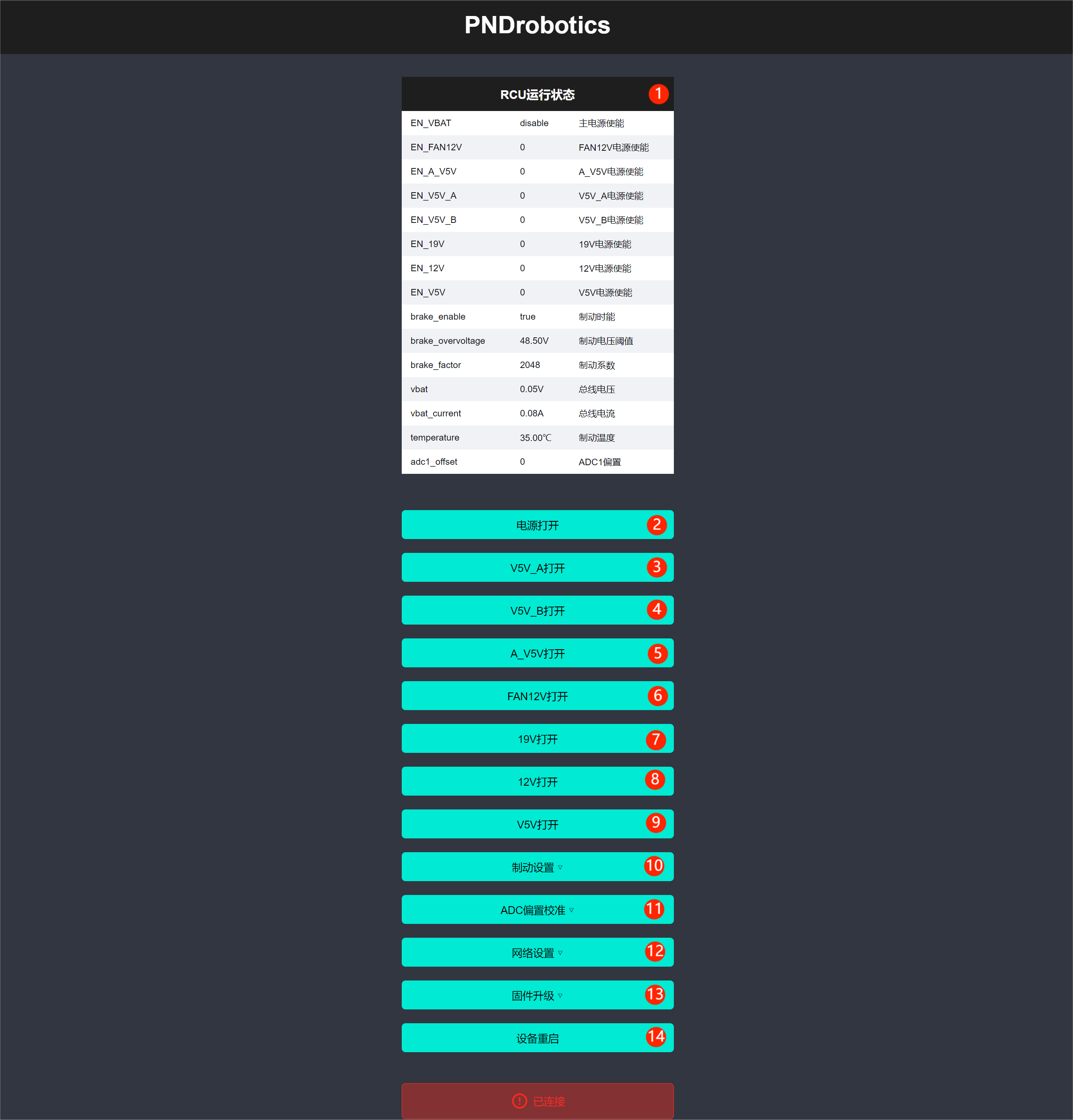
| Serial Number | Button/Menu | Interface Description |
|---|---|---|
| 1 | RCU running status | Current RCU running status/configuration information. |
| 2 | Power on | RCU bus voltage control, red is on state. |
| 3 | V5V_A on | RCU's V5V_A power control, red is on state. |
| 4 | V5V_B on | RCU's V5V_B power control, red is on state (reserved). |
| 5 | A_V5V on | RCU's A_V5V power control, red is on state (reserved). |
| 6 | FAN12V on | RCU's FAN_12V power control, red is on state. |
| 7 | 19V on | RCU's 19V power control, red is on state. |
| 8 | 12V on | RCU's 12V power control, red is on state. |
| 9 | V5V on | RCU's V5V power control, red is on state. |
| 10 | Braking setting | RCU braking function configuration, click to perform specific configuration. |
| 11 | ADC offset calibration | RCU ADC offset calibration function, click to perform specific configuration. |
| 12 | Network setting | RCU network configuration, click to perform specific configuration. |
| 13 | Firmware upgrade | RCU firmware upgrade function, click to perform specific configuration. |
| 14 | Device restart | Restart the RCU. |
Braking Setting Description
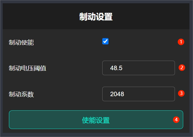
| Serial Number | Button/Menu | Interface Description |
|---|---|---|
| 1 | Braking enable | Check to enable braking function. |
| 2 | Braking voltage threshold | Adjust the braking voltage threshold, which is generally about 1V higher than the main power supply voltage. |
| 3 | Braking coefficient | Value range is 0~4096, adjust the braking ratio. |
ADC Offset Calibration Description
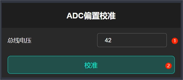
| Serial Number | Button/Menu | Interface Description |
|---|---|---|
| 1 | Bus voltage | Current main power supply voltage (measured using an external instrument). |
| 2 | Calibration | Perform calibration according to the currently set bus voltage. |
Network Setting Description
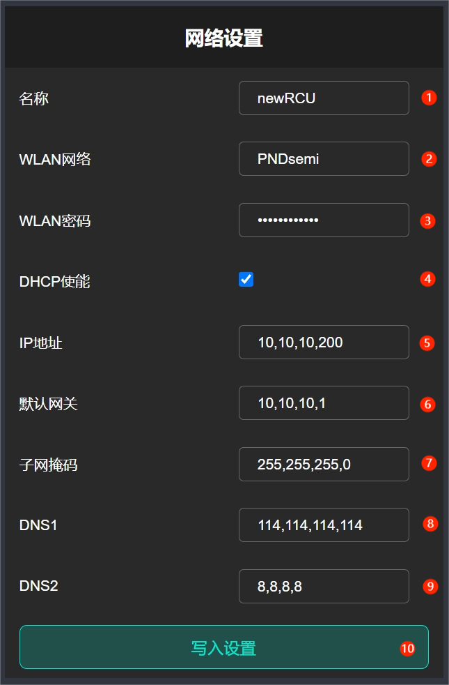
| Serial Number | Button/Menu | Interface Description |
|---|---|---|
| 1 | Name | Configure the current RCU name. |
| 2 | WLAN network | Wi-Fi network name. |
| 3 | WLAN password | Wi-Fi network password. |
| 4 | DHCP enable | Check to enable DHCP function to automatically obtain IP. |
| 5 | IP address | Configure the static IP address of the wired network. |
| 6 | Default gateway | Configure the static default gateway of the wired network. |
| 7 | Subnet mask | Configure the static subnet mask of the wired network. |
| 8 | DNS1 | Configure the static DNS1 of the wired network. |
| 9 | DNS2 | Configure the static DNS2 of the wired network. |
| 10 | Write configuration | Click to write the current network configuration information. |
Firmware Upgrade Description
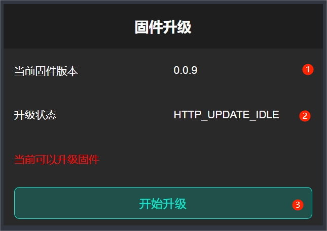
| Serial Number | Button/Menu | Interface Description |
|---|---|---|
| 1 | Current firmware version | View the current firmware version. |
| 2 | Upgrade status | Display the upgrade status. |
| 3 | Start upgrade | Click to start the upgrade. |